The CAN Daughterboard
The CAN Daughterboard is an open-hardware CAN/SPI/I2C/Serial board designed by the Trustworthy Systems group, that can be mounted below the power supply module of the TK1-SOM. It provides two CAN buses implemented with MCP2515 (on the TK1-SOM’s SPI bus) and voltage conversion for the two serial ports.


Mounting
The board attaches to the bottom of a TK1-SOM via the expansion connector. No further work should be needed to enumerate the device given a kernel supporting GPIO chipselects.
Note the unpopulated standoff holes on the rightmost image above — it is possible to fit a standoff of the same type already installed in the TK1-SOM to stabilize the ‘tower’ making it easier to work with.
The part numbers of the standoffs between the CAN daughterboard and TK1 is the same as is already used between the CPU & GPU board. Order codes:
- STANDOFF - HEX M2.5 x 16MM ALUMINUM M-F (M2111-2545-AL) between pcb standoff
- SCREW - M2.5 x 5 MM SS PAN HEAD PHILIPS (92000A103) bottom pcb screw
Using Linux with this daughterboard for CAN
(hello world & testing) See Using CAN on L4T through an MCP251X
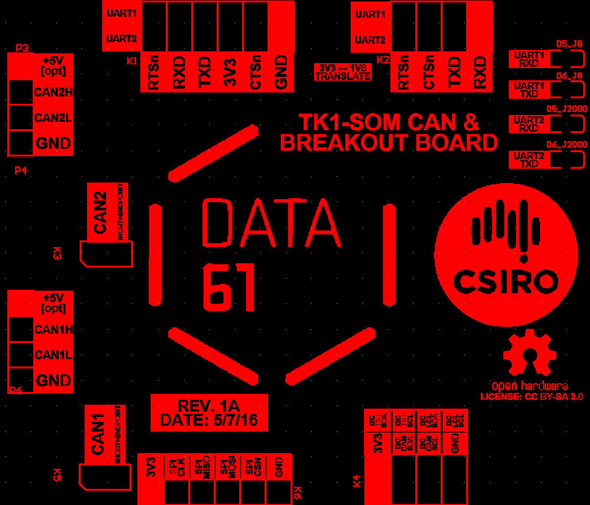
Pinout detail
The font on the silkscreen indicating pins is difficult to see once the tower is assembled (wasn’t enough space on the top) - See this picture (view taken from bottom):
Warning - UART Level Converter:
- If using the level converter on the board, and if you are getting junk from your 3V3 serial cable, read this:
- Unfortunately there is an issue with these level converter chips, in some impedance situations the rise time is much worse than indicated on the datasheet. Basically, with some serial cables the converter will garble signals at a high baud rate (> 57600).
- This can be circumvented by changing your u-boot and extlinux to use a slower baud rate. 9600 is very safe, anything up to about 57600 should be fine — start slow and work up.
If you need the faster baud rates (or don’t want to change the default settings), use a 1V8 USB-TTL cable and plug it straight into the TK1 as usual. This will be fixed in a future revision.
TK1 SOC Connections
Useful for writing drivers - this is a list of which pins on the board correspond to which SOC pins:
All I2C signals operate at 3V3 on their 0.1” headers, except I2C_CAM which is selectable from 1V8<->3V3 in software.
| PIN | BALL | PERIPHERAL ID |
|---|---|---|
| I2C_CAM_SCL | AF8 | I2C3_CLK |
| I2C_CAM_SDA | AG8 | I2C3_DAT |
| I2C_TK1_SCL | Y2 | I2C2_CLK |
| I2C_TK1_SDA | AA2 | I2C2_DAT |
| I2C_LOCAL_SCL | P6 | I2C1_CLK |
| I2C_LOCAL_SDA | M6 | I2C1_DAT |
All SPI signals out of the TK1 are at 1V8, but are translated to 3V3 by the board (the 0.1” header operates at 3V3)
| PIN | BALL | PERIPHERAL ID |
|---|---|---|
| SPI_CLK | AG15 | SPI1A_SCK |
| SPI_MISO | AL18 | SPI1A_DIN |
| SPI_CSN | AL16 | SPI1A_CS0 |
| SPI_MOSI | AK17 | SPI1A_DOUT |
All UART signals out of the TK1 are at 1V8, but are translated to 3V3 by the board. Note that UART signals will only be present on the board outputs if the uart is actually jumpered to the converter!
| PIN | BALL | PERIPHERAL ID |
|---|---|---|
| J8_RTSn | V5 | UD3_RTS |
| J8_CTSn | V9 | UD3_CTS |
| J8_TXD | V4 | UD3_TXD |
| J8_RXD | U4 | UD3_RXD |
| J2000_RXD | L0 | UART2_RTS_N |
| J2000_TXD | M8 | UART2_CTS_N |
| J2000_CTSn | M1 | UART2_TXD |
| J2000_RTSn | P4 | UART2_RXD |
Note that TXD (1V8) is translated to TXD (3V3). NOT TXD (1V8) <-> RXD (1V8). This means that the jumper from the TK1-SOM should go from it’s TX to RX on the daughterboard for a standard ftdi pinout to work.
Note that GPIOs aren’t actually brought out by the board but they are used by the CAN controller (diagram below).
| PIN | BALL | PERIPHERAL ID |
|---|---|---|
| TK1_GPIO0 | AF29 | GPIO3_PS.05 |
| TK1_GPIO1 | AA26 | GPIO3_PT.00 |
| TK1_GPIO2 | AC30 | GPIO3_PS.06 |
| TK1_GPIO3 | AA31 | GPIO3_PS.02 |
| TK1_GPIO4 | V28 | GPIO3_PS.03 |
| TK1_GPIO5 | W31 | GPIO3_PR.00 |
| TK1_GPIO6 | AB31 | GPIO3_PR.06 |
| TK1_GPIO7 | Y27 | GPIO3_PS.04 |
CAN Controller (MCP25625) GPIO Usage:

Construction Information
| Schematic | canboard_v3.pdf |
| PCB Sources Repository | https://bitbucket.csiro.au/projects/OH/repos/tk1som-can-daughterboard |
| Gerber Files (in repo also) | Tegra_CANboard_tofab_v1.zip |
| BOM (in repo also) | CanBoardBOMDraft1.xlsx |
Construction notes
Components R6, R14, R19, R23 should NOT be mounted. R6 and R19 are pull-up resistors that were found to cause signal integrity issues, the other 2 resistors when mounted will supply 5v to the CAN lines and are optional.