TK1-SOM Hardware Modifications
Adding a second UART connector
The issue
If you are using our IO-Daughterboard, this is unnecessary; instead a straight-line passthrough jumper is used to hook up to level converters on the daughterboard.
The TK1-SOM has a secondary UART connection, however it’s a bit of a pain to get to as a normal jumper won’t fit sandwiched between the boards (below left), and you can’t get to the connection from the top because of the fan & heatsink (below right).


What it looks like
Viewed from the bottom of the CPU board, the secondary UART is the 4 unpopulated pins just under the ethernet jack pins (see below):

Right-angle connectors?
Initially I looked at normal right-angle 0.1” headers, but they don’t fit in either direction!


Above left: you can’t connect a jack as there is no clearance to the mezzanine connector. Above right: the pins will likely short with the ethernet jack pins.
Solution: modify a dual-row header..
A normal dual-row 0.1” header looks like this:
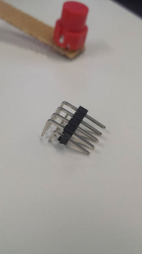
But we only need it for clearance - which we can do by just taking out the bottom 2 rows of pins:
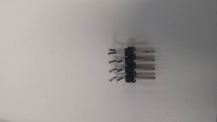
(It’s easiest to use pliers to push the pins out a little bit, bend them, and then pull them all the way out)
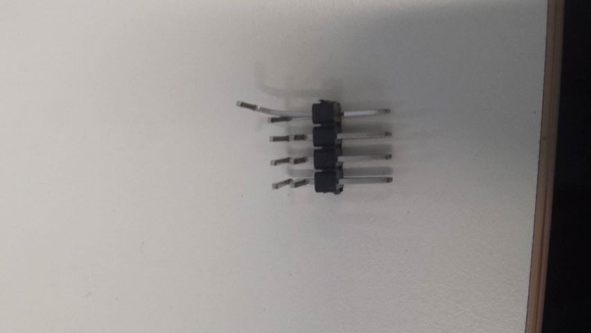
Eventually, you end up with this (Only the top row left):
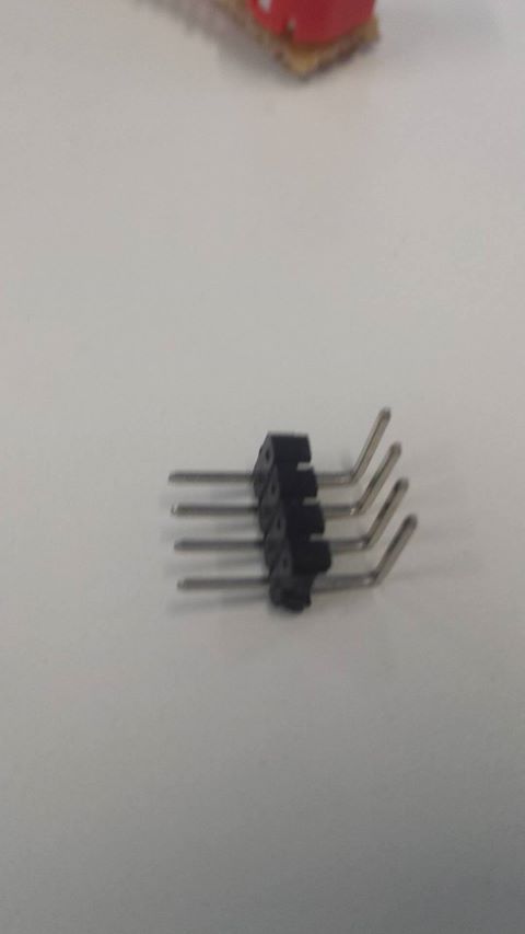
Now you can solder the pins on (make sure the pins are directed toward the ethernet jack so there’s enough clearance!)
Make sure not to use too much heat in this step, there are a few 0201 components nearby which can easily come off just because of the nearby heat. Also be sure to keep the iron angled away from the connectors as it is quite easy to accidentally melt them.
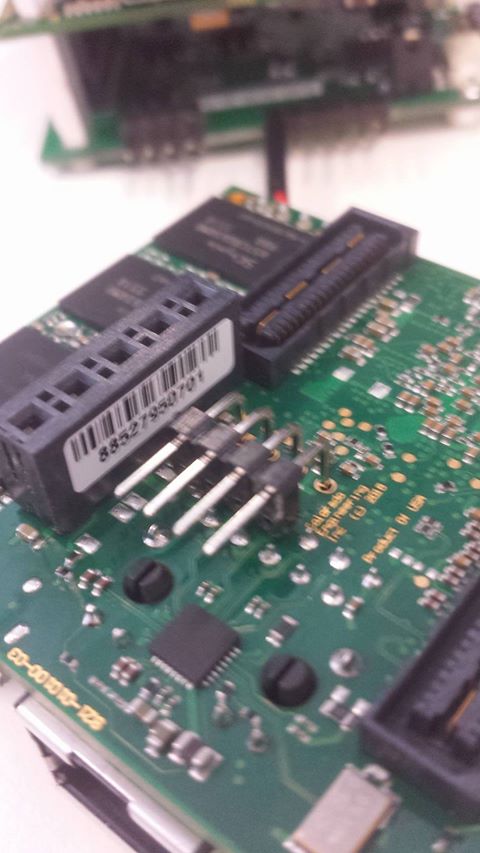
Once done, put the TK1-SOM back together and you have some easily accessible UART pins:

The pinout & levels are described in the TK1-SOM reference guide - this connector is called J2000. (Pin 1 is the square pad)
Note the 1V8 logic levels!