This page is archived and is no longer receiving updates.
It remains here because some of the content may still be useful.
Using the Saleae Logic Pro 8 to debug a CAN bus
Introduction
This page is a quick write up of how we used a logic analyzer to help solve a message loss issue when using a CAN bus. We had two TK1-SOMs connected together on a CAN bus. One of them runs Linux natively and the other runs an seL4 CAmkES application that receives CAN frames and then prints them out. We found that although the CAmkES application could correctly receive and reply to individual CAN frames, when frames were being received at the maximum rate of the bus the CAmkES application would only print out the first, last and occasionally a frame in the middle. Read more about CAN here, and here is the Saleae Logic Pro 8 site. Information about the TK1-SOM daughter board that we use is here.
Setup
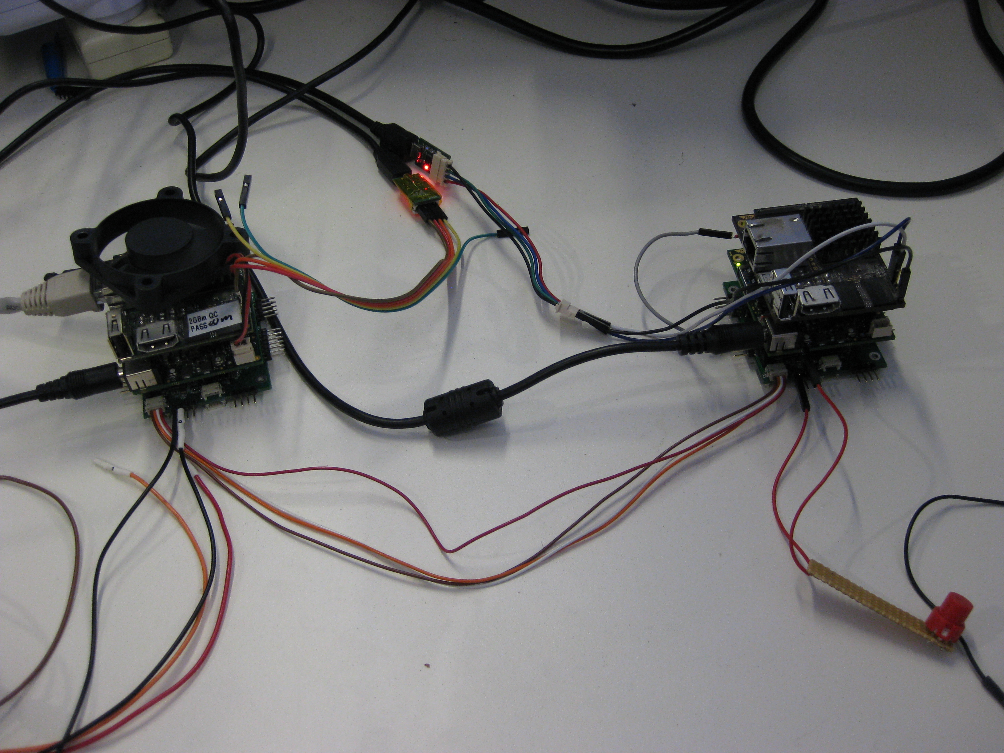
Each of the TK1-SOMs have a daughter board with a MCP25625 CAN controller on them that can communicate with the processor over SPI. When a controller receives a CAN message it notifies the processor by interrupting it over a GPIO line. The processor then reads the CAN message out of the controller over SPI. We can use the LogicPro8 to probe the CAN bus, the SPI bus and also the GPIO pin that the interrupt is received on to get a feel for what is going on.
Connecting to the CAN bus
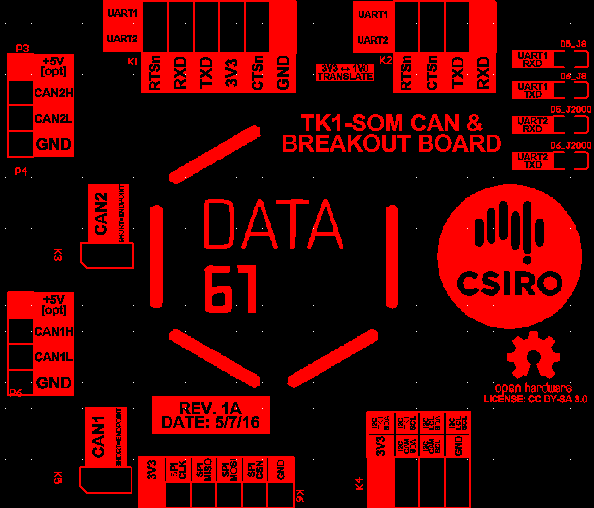
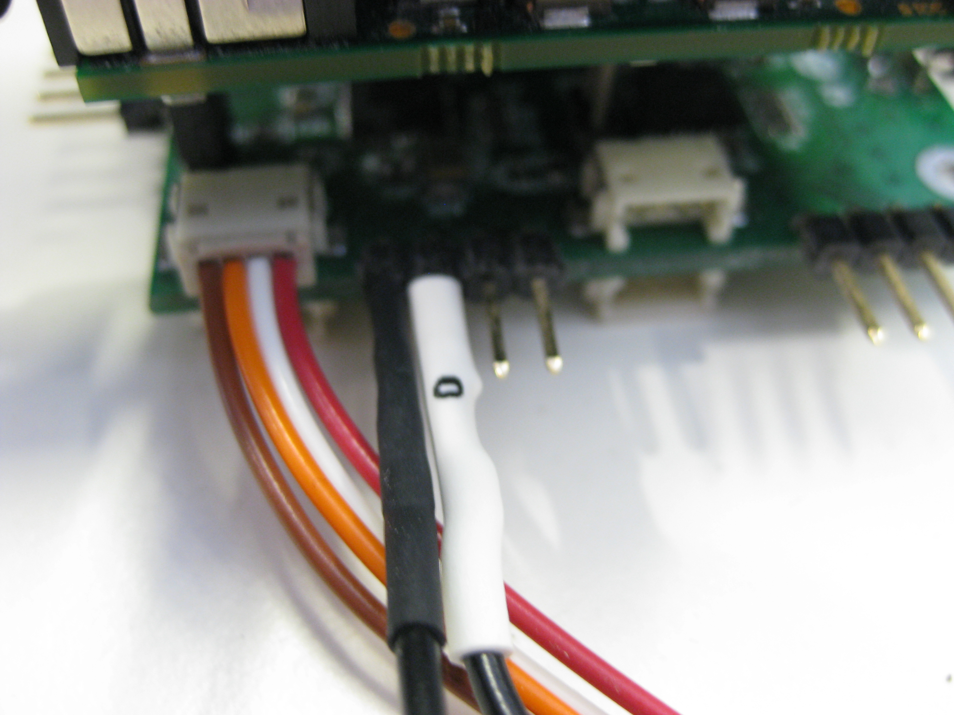
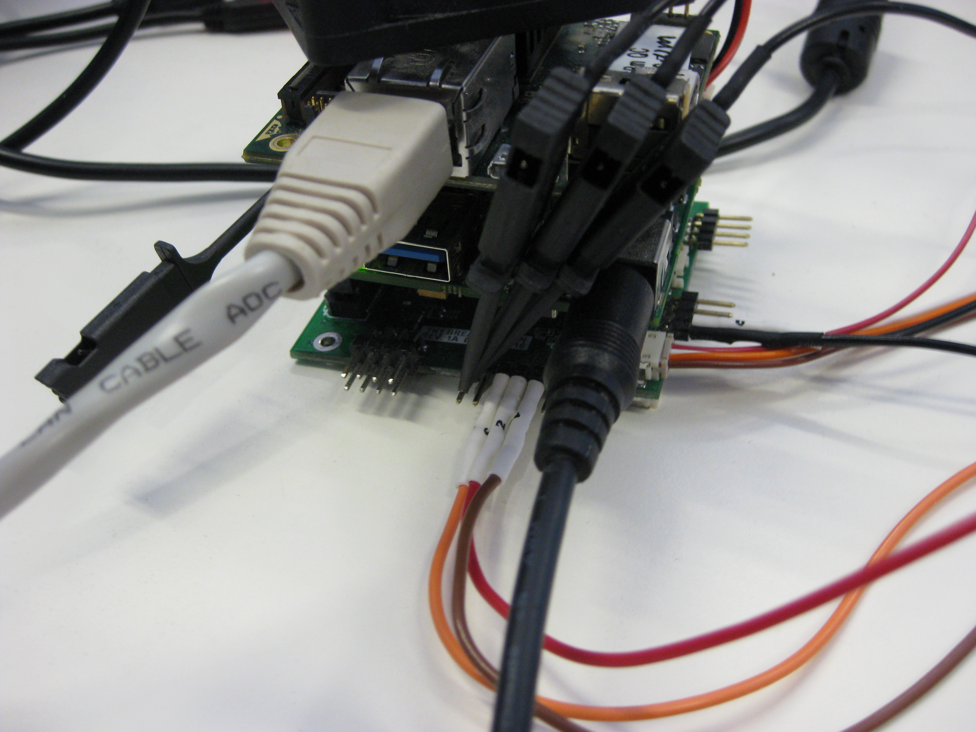
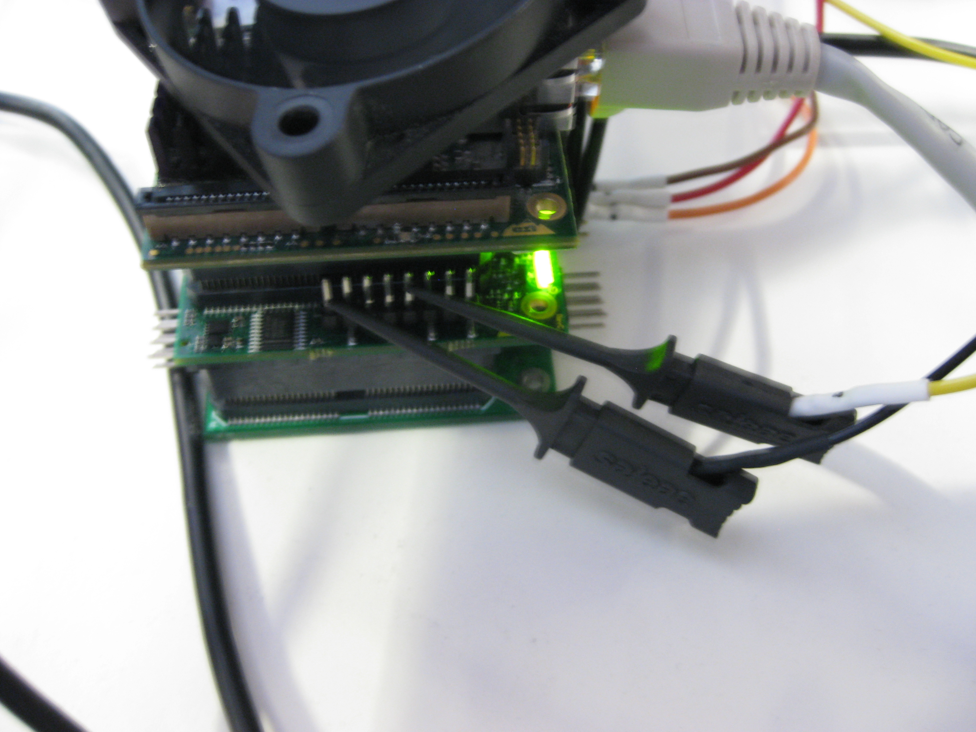
On our daughter board (schematic above), our CAN bus pins are CAN1H, CAN1L and GND. The Logic pro only needs to be plugged into CAN1L and GND in order to decode CAN frames. We connect Channel 0 of the Logic pro as shown: (Note that the schematic above shows the bottom of the daughter board. So the order of the pins in the photo is reversed)
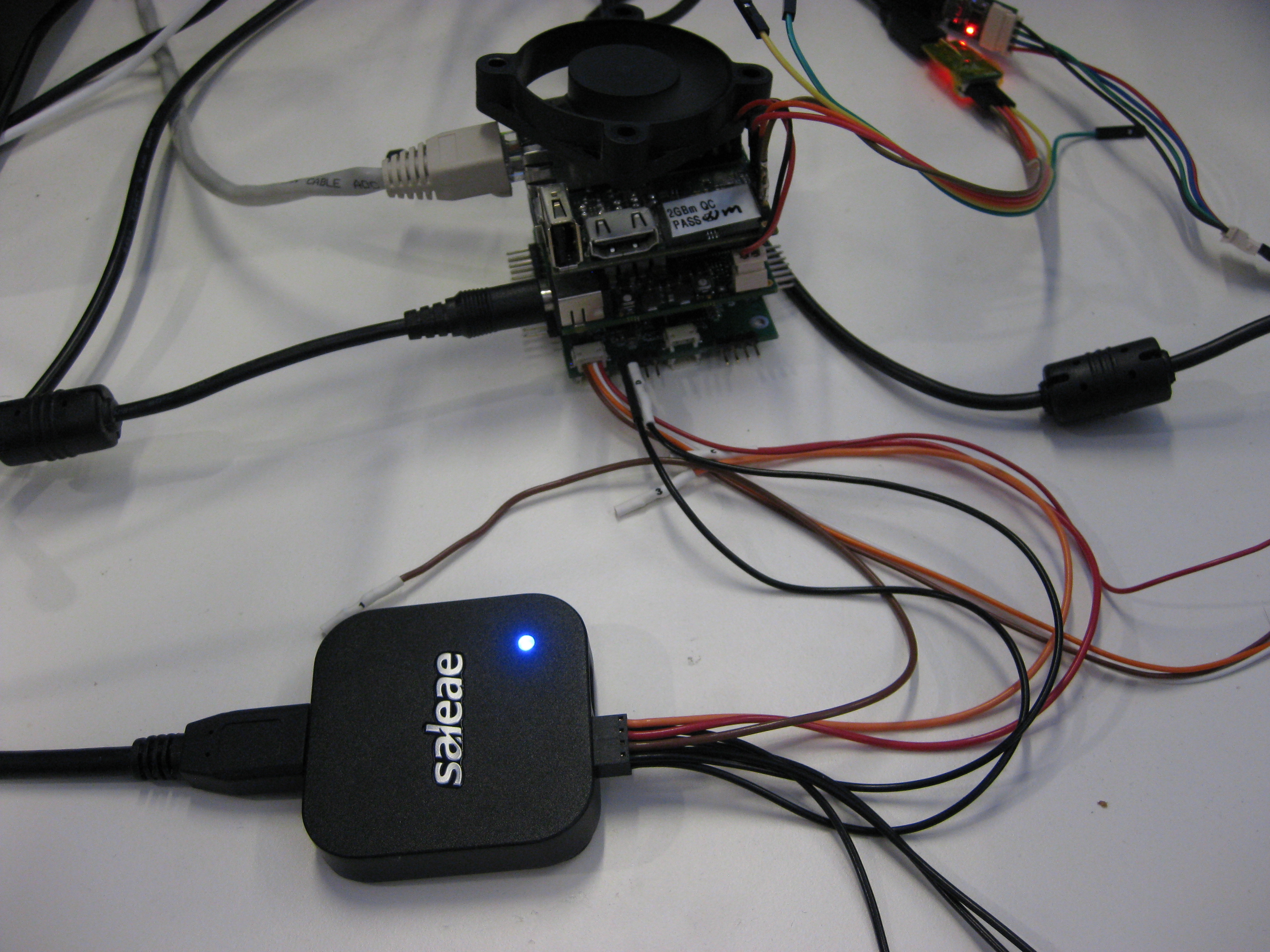
Saleae provides the Logic software which is used to collect and analyse data.
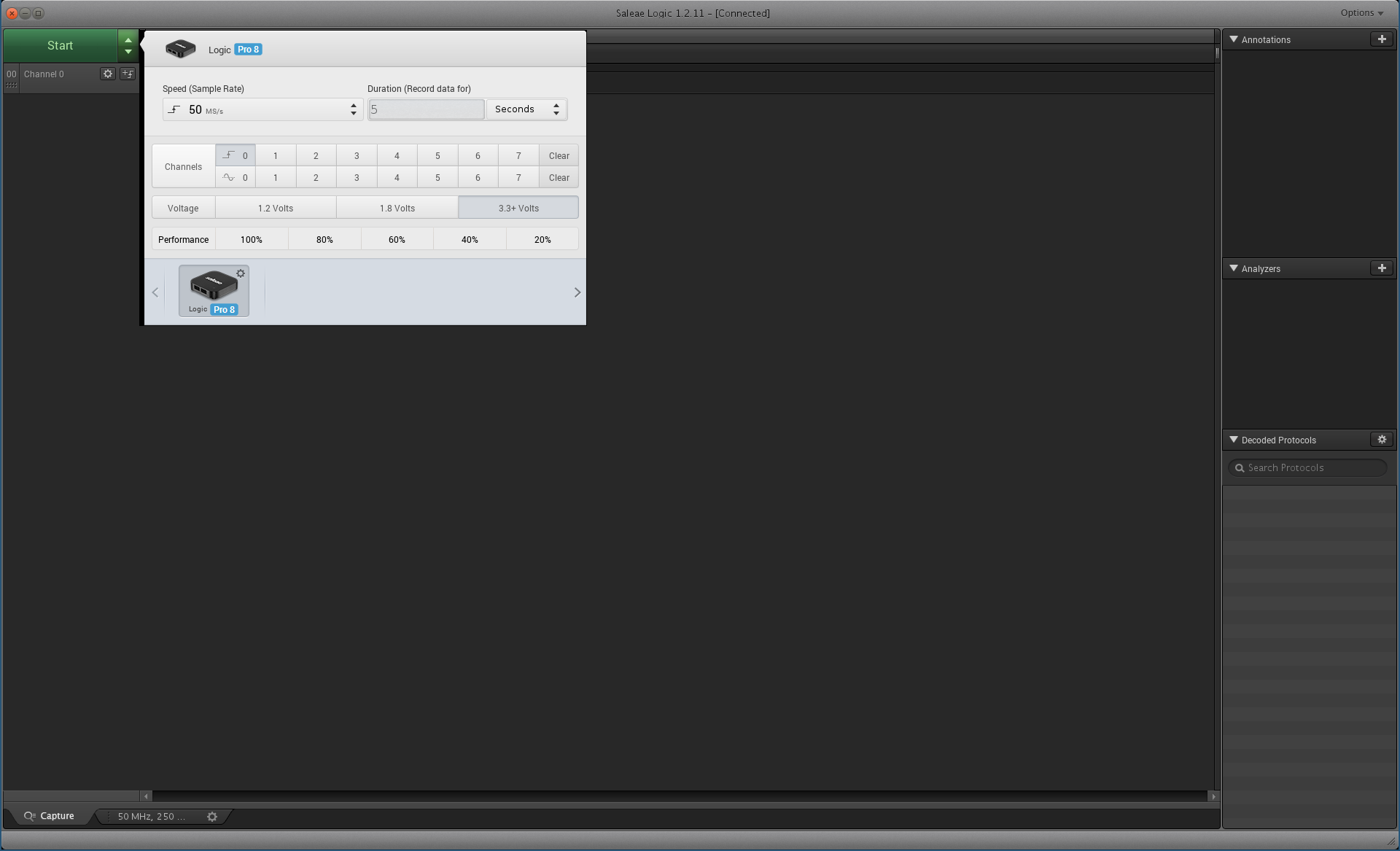
We configure Logic to collect at a rate of 50MS/s on channel 0 with 3.3+V
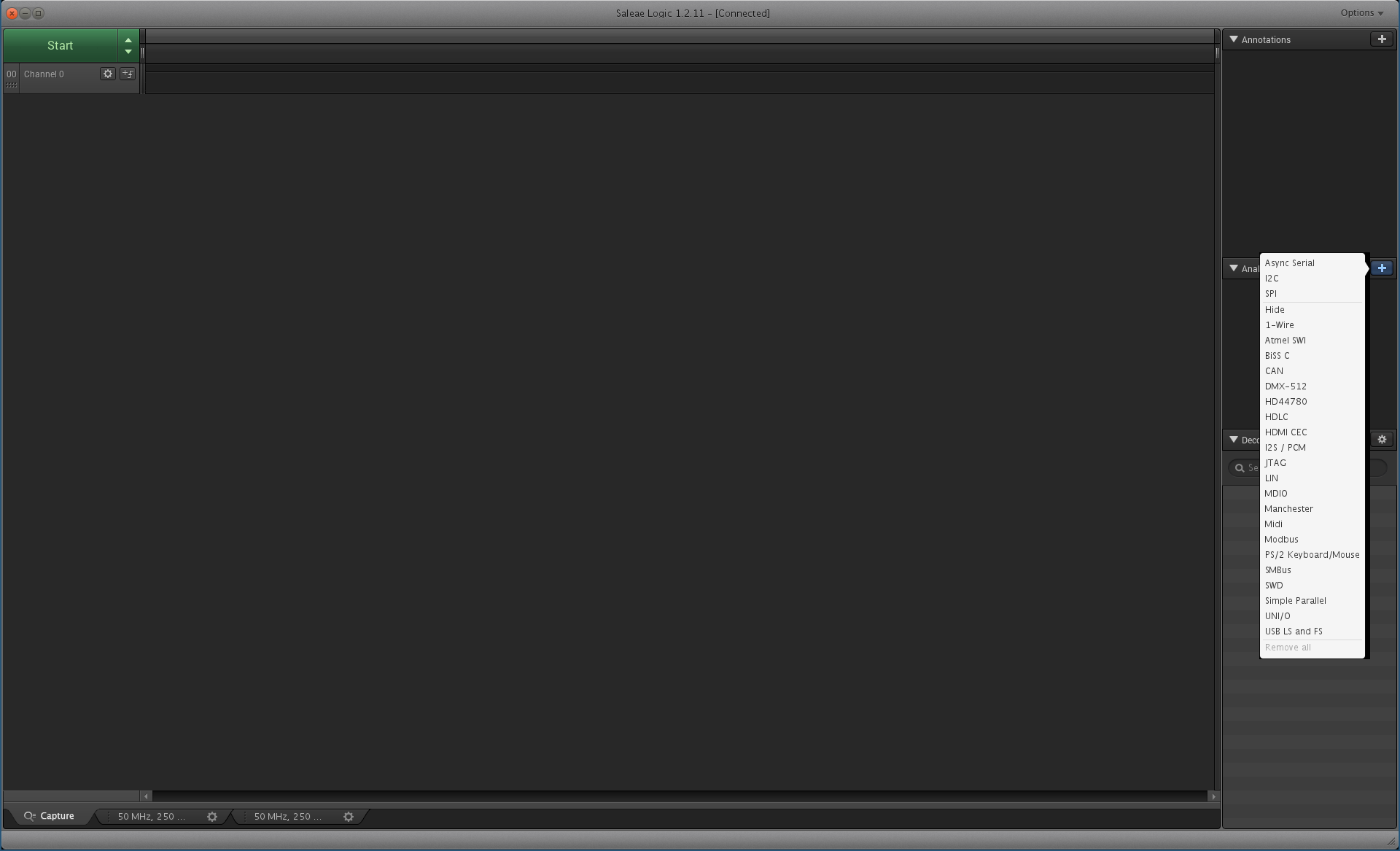
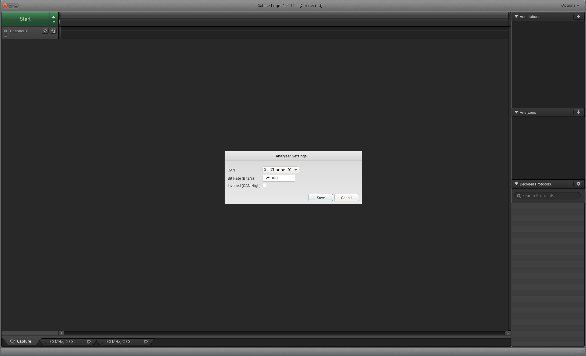
We add CAN as an analyser for Channel 0 and set the bitrate to 125000 which is what our TK1s are configured to use.
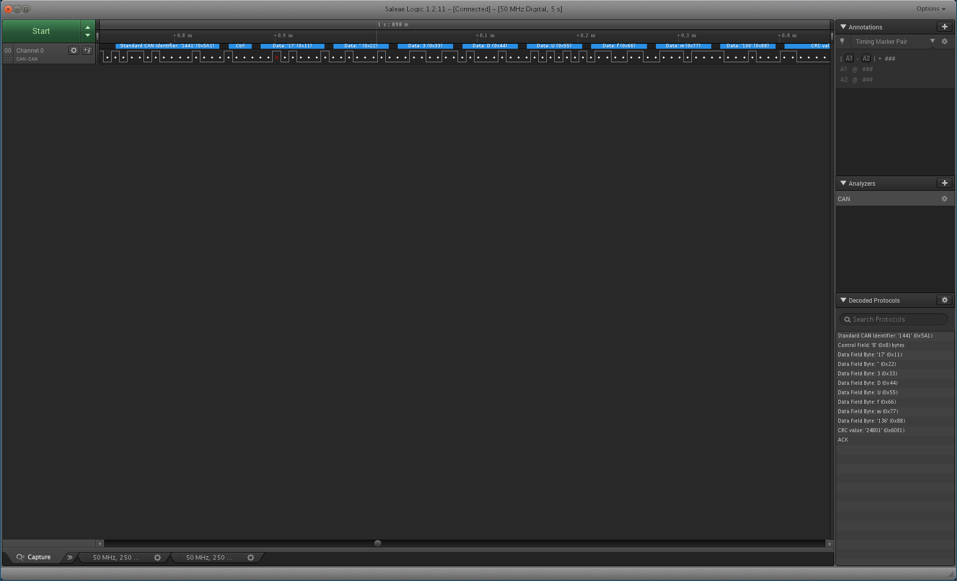
We press start and then send one CAN message from the Linux TK1 to the seL4 TK1.
Native Linux:
ubuntu@tegra-ubuntu:\~$ cansend can0 5A1#11.22.33.44.55.66.77.88

seL4: Recv: error(0), id(5a1), data(11, 22, 33, 44, 55, 66, 77, 88)
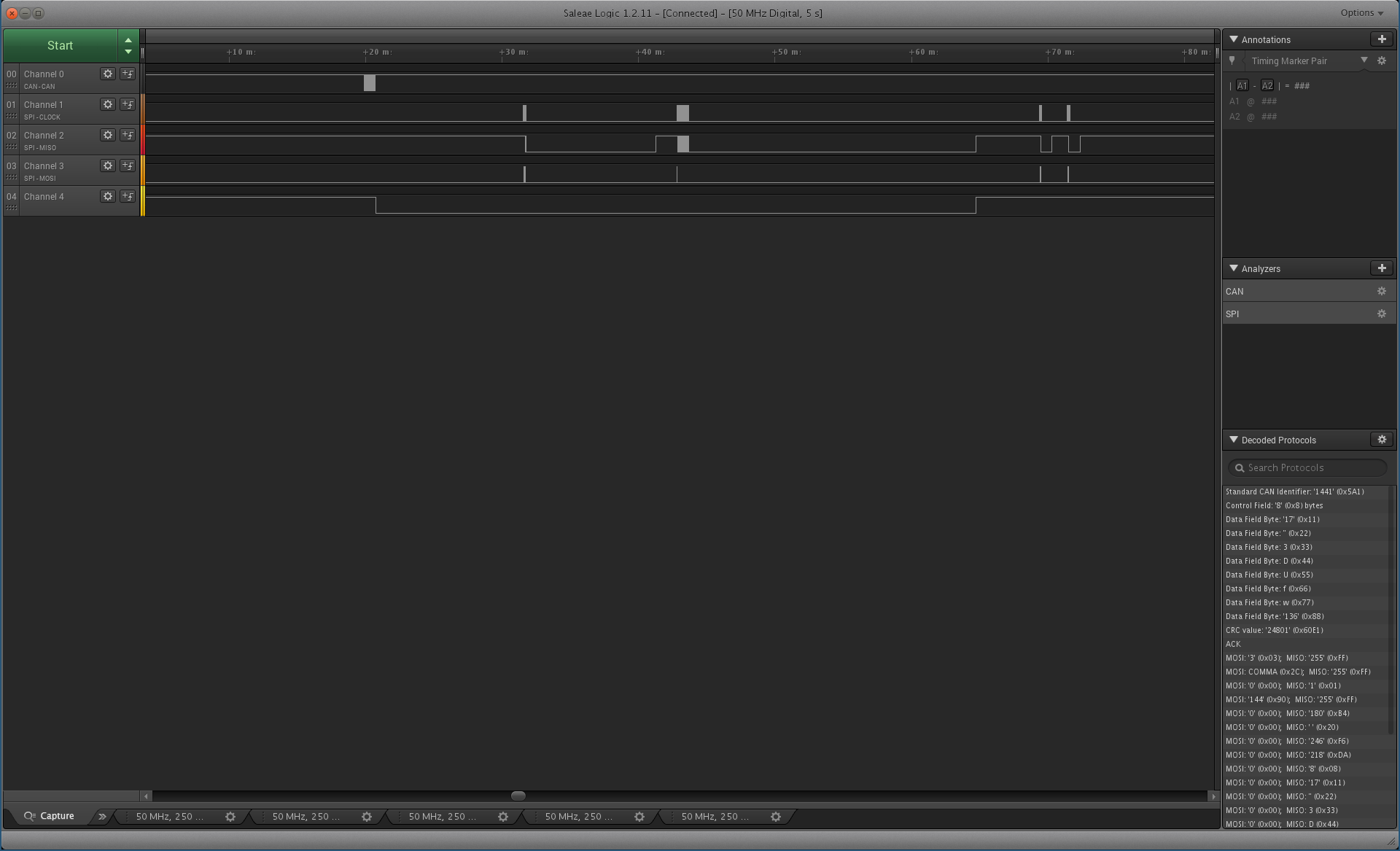
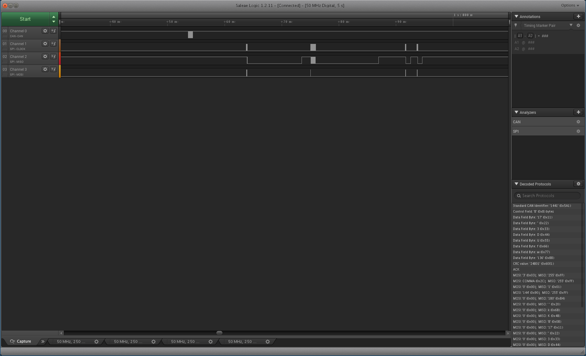
In Logic we see that we measured the CAN message being transmitted over the bus. On the side under Decoded protocols Logic reports the fields of the message that was sent.
Connecting to SPI
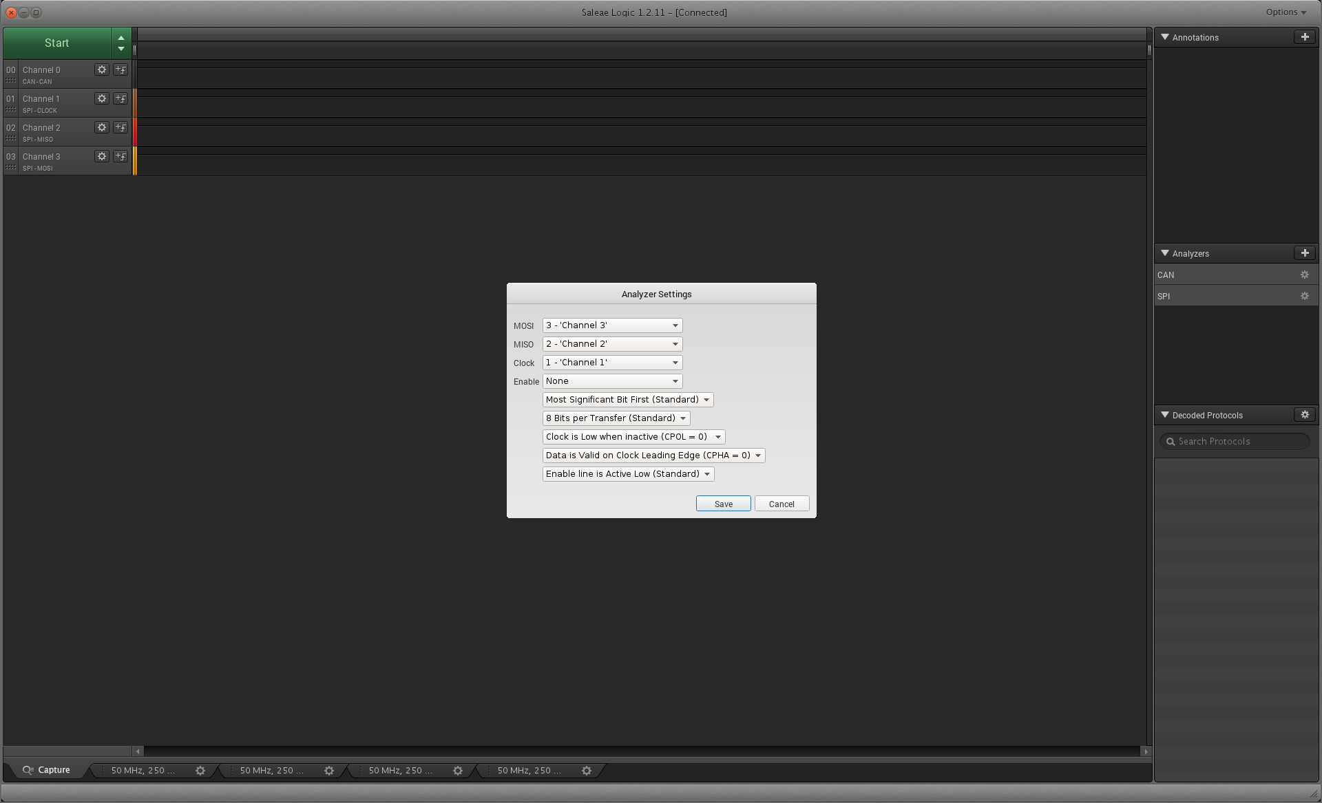
We now connect to the SPI bus. To do this we need to measure the CLK, MOSI and MISO. (These pins can be found at the bottom of the schematic). We connect the probe to them as follows:
In Logic we add the new channels and configure a SPI analyser for them.
After running the scan again while sending a CAN message we now see the CAN frame sent on the bus followed by a few SPI transactions between the Processor and CAN controller.
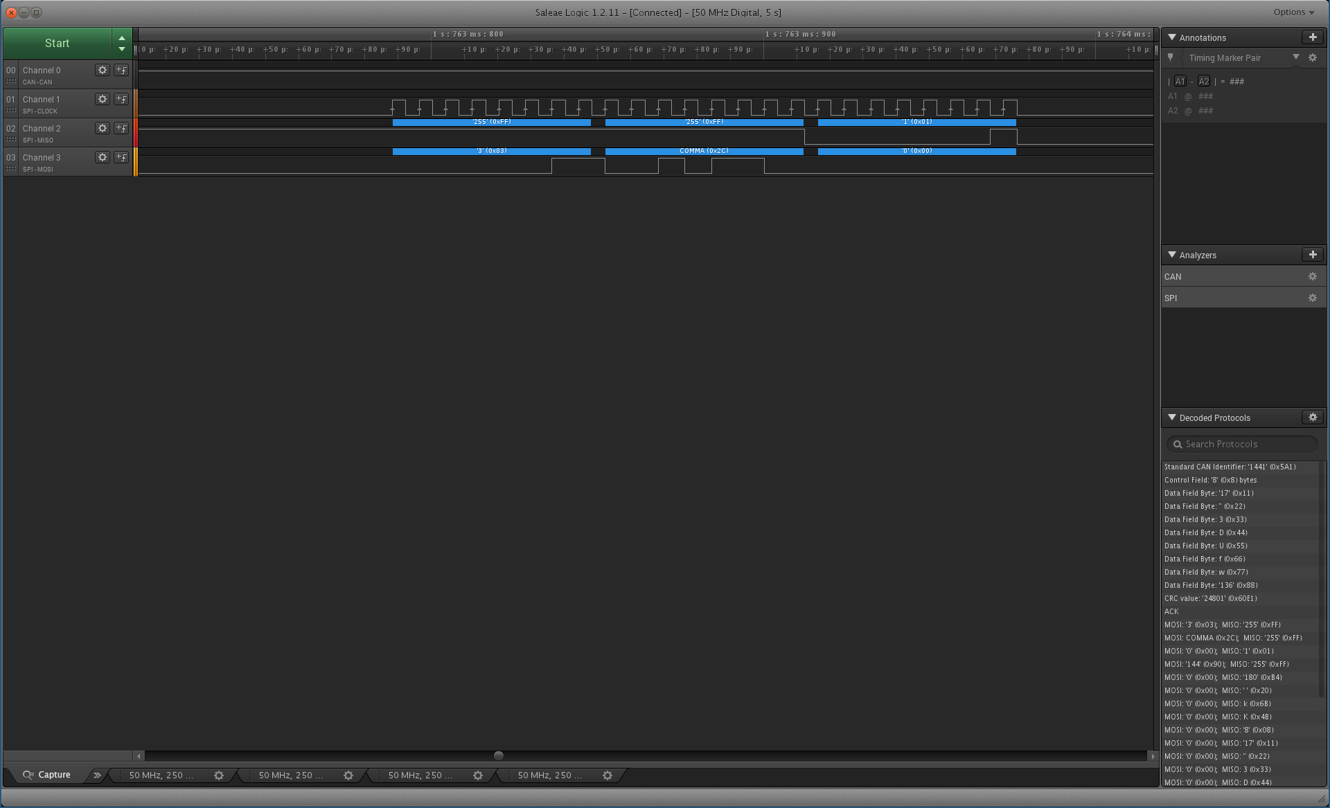
Zooming in on a single SPI transaction we see that the CAN driver send 0x03, 0x2C and the CAN controller respond with 0x01. This corresponds to Read register 0x2C (Interrupt flag register) and the register value being returned as 0x01 (Message received). Under decoded protocols you can see both CAN messages and SPI messages that were sent.
GPIO Interrupt line
We finally connect the probe to the interrupt line. The daughter board configures the CAN controller to interrupt over GPIO3 which is exposed as Pin 4 on pinout J5 as described in the TK1-SOM Reference guide. This is at the back of the TK1 relative to our setup and we connect the probe as shown:
We capture a message being sent again and now we can see the CAN message being sent, the controller interrupting the GPIO line and then the processor responding to the interrupt with SPI transactions. Eventually the interrupt line is reset once the processor has read out the received CAN message from the CAN controller.